
Thankselectrodist wrote:John, I will post a picture of the new lamp solution for you when I get a chance to snap a shot of it.
DC Motor for DIY 16mm Telecine?
Moderator: Andreas Wideroe
I don't know this particular motor of course, but the datasheet ( http://tinyurl.com/2syqjy ) shows them connected to ground externally. If they are also connected internally, it will not make a difference...but worth a try.electrodist wrote:5 is connected to the third (side) lead of the pot. 6 is connected to the PSU V- output. Should these be grounded on the chassis as well? The PSU is grounded through screws onto the chassis metal as is the ground lead from the AC cord.
Frank
Off all the things I've lost, I miss my mind the most.
-
electrodist
- Posts: 27
- Joined: Tue Nov 06, 2007 8:32 pm
- Location: Chicago, IL
- Contact:
So the multimeter tests show that the current for the motor power is brought down with the speed controller setting. At top speed I can get 60 watts power, though it doesn't need this. At 1/5 speed it stalls out and is only drawing 6-7 watts power. The pwm controller connected to the motor power and ground shows similar characteristics. I wired it exactly as illustrated on hte spec sheet. The rep at Anaheim Automation says that this current decrease with a speed controller is typical of all brushless DC motors. Does this sound right to you guys?
I'm a little confused here, what do you mean by PWM? Are you assuming the internal speed control is just a PWM, or have you hooked up an external PWM control? The internal control will be (or at least it should be) a lot more sophistcated than just a PWM. It will be a circuit which monitors rotation phase and generates an AC waveform for the motor. This same circuit should monitor speed and allow the motor to draw more power to maintain speed under load. BTW a brushless DC motor is actually an AC motor with electronic control of the current in the windings.electrodist wrote:So the multimeter tests show that the current for the motor power is brought down with the speed controller setting. At top speed I can get 60 watts power, though it doesn't need this. At 1/5 speed it stalls out and is only drawing 6-7 watts power. The pwm controller connected to the motor power and ground shows similar characteristics. I wired it exactly as illustrated on hte spec sheet. The rep at Anaheim Automation says that this current decrease with a speed controller is typical of all brushless DC motors. Does this sound right to you guys?
If you add an external PWM for the motor power, then this will screw it completely.
Frank
Off all the things I've lost, I miss my mind the most.
-
electrodist
- Posts: 27
- Joined: Tue Nov 06, 2007 8:32 pm
- Location: Chicago, IL
- Contact:

Thanks! I appreciate the photo.electrodist wrote:Here is my lighting solution John. The MR16 holder is from a Eiki ST/M. The rest is simple. Just a ultra-white interior with a 45 degree angle and opal glass at the end. The bulb I use is a 75watt 12VAC MR16.
Happy Holidays,
John
History frozen in the frame of 8mm
Ebay has much for such motors etc
Ebay is a good source. I picked up some 12 & 24v power supplies, 5 amp, Siemens. Some are new and used.
-
electrodist
- Posts: 27
- Joined: Tue Nov 06, 2007 8:32 pm
- Location: Chicago, IL
- Contact:
Yes ton of the transformers on Ebay, though I decieded to get this one:
http://www.semperlite.com/Prod_lvt_main ... ductID=840
It fits on the chassis using preexisting holes. See it behind the motor.

On another thread there was discussion about outfitting a halogen light with a regulated computer PSU. Can halogen run off of DC?
http://www.semperlite.com/Prod_lvt_main ... ductID=840
It fits on the chassis using preexisting holes. See it behind the motor.
On another thread there was discussion about outfitting a halogen light with a regulated computer PSU. Can halogen run off of DC?
-
electrodist
- Posts: 27
- Joined: Tue Nov 06, 2007 8:32 pm
- Location: Chicago, IL
- Contact:
So I got a new pulley combination, now a 18:90 instead of an 18:50. The projector has no problem running at 4FPS to 14FPS...but I broke whatever connects the motor shaft to the drive, so I just get a grating noise when the motor is on. The new larger diameter gear on the camtank amplified the play in the gear, and perhaps the belt was too tight. Got a new belt and motor on the way.
Also, I built the simple infrared optical triggering circuit that is on Frank's page and connected the output to a mouse. It works as far as sending the voltage drop to the mouse, but in Capturemate I am limited to about 6FPS input with the signal. I can physically click the mouse faster than that in bursts, all recognized by Capturemate. Should I need more complicated circuitry to get a cleaner signal for output to a mouse or is the problem most likely with mouse or IR emitter detector (same as Franks)?
Can't wait to get a camera test done. This stuff is so far away from video editing (though very educational)!
Your timing slot may not be big enough. The faster the projector goes, the shorter period of time the slot is. It needs to be large enough such that at your maximum required speed the switch is "closed" for around 20ms. The mouse I tried ignored switch closures less than 16ms (because of the switch debouncing circuit). At 10fps for example, a point on the circumference of the shutter blade will move a full rotation in 100ms. So to produce an on-time of 20ms, we need the slot to be 1/5th of the angular dimension...or 360/5=72 degrees.electrodist wrote:Also, I built the simple infrared optical triggering circuit that is on Frank's page and connected the output to a mouse. It works as far as sending the voltage drop to the mouse, but in Capturemate I am limited to about 6FPS input with the signal. I can physically click the mouse faster than that in bursts, all recognized by Capturemate. Should I need more complicated circuitry to get a cleaner signal for output to a mouse or is the problem most likely with mouse or IR emitter detector (same as Franks)?
I would gradually open up your slot until you get the desired performance.
Frank
EDIT: The solution for the optical switch on my webpage was not designed to work with a mouse, but with a triggerable machine cam...hence the slot is smaller.
Off all the things I've lost, I miss my mind the most.
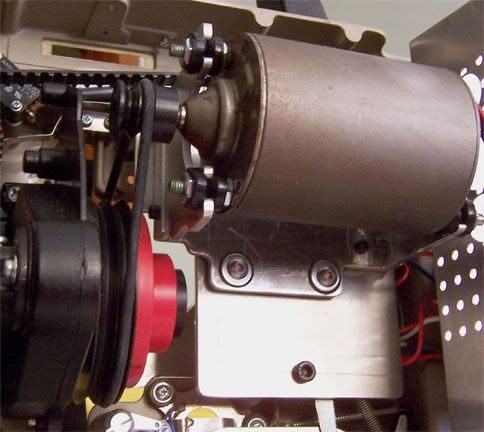
electrodist wrote:...but I broke whatever connects the motor shaft to the drive, so I just get a grating noise when the motor is on. The new larger diameter gear on the camtank amplified the play in the gear, and perhaps the belt was too tight. Got a new belt and motor on the way.
Personally, I'm not a big fan of the extended motor shaft I see in your photo. I realize this was done to get the 2 pulleys in alignment, but there is the potential for a lot of lateral stress on the motor shaft, which with a tight belt, is probably what sheared the shaft. Having an extended shaft also tends to increase shaft end runout play, which can considerably shorten the life of the front shaft bearing of the motor. I know the original motor uses an exteded shaft as well, but the shaft is pretty thick (8mm) and the motor uses roller bearings, which can stand up to much more lateral force than a simple bushing bearing can.
As a suggestion, I would place some spacers between the motor plate you fabricated and the modified original motor housing mount to bring the 2 pulleys into alignment. You'll use a much shorter shaft and put a lot less stress on it.
Here's a quick photo of what I'm doing with a DC motor:
JJ
History frozen in the frame of 8mm
-
electrodist
- Posts: 27
- Joined: Tue Nov 06, 2007 8:32 pm
- Location: Chicago, IL
- Contact:
Thanks Frank and John!
Frank, I will give that idea a whirl. Thanks for the clear technical explanation. I am using the shutter sans blades as my disc. This will allow me to mount the circuit onto the camtank housing.
John, very elegent design with the motor mount. Looks very sturdy. What tools did you need to make it.
I went with the original Eiki motor mount so I wouldn't have to make so many parts. I only have a drill press, table saw, and dremel at my disposal. As for the spacers, what do you think would be the sturdiest solution:
-Cutting a piece of wood to fit flat between the original motor mount and the new face plate. This would require cutting a square hole for the motor body. This solution would have the most contact area.
-Using the squared hollow aluminum tubing that can be found at home depot. I think each side is 1 inch wide with this stuff. I place these between the motor mount and face plate in a square configuration around the motor. This solution would have less contact area than the wood but provide a more rigid surface.
-Use the things sold at online parts stores called spacers. These come in square, hexagonal, and circular varieties, and are prethreaded for the screws. This solution would provide contacts at only the four points where the screws are but being thicker metal would be the most rigid contact.
-Other suggestions?
The metal faceplate is fairly rigid steel, though it is thin. Here is another view.
I think that I will need to keep the shaft extender on the camtank end so I only have to move up an inch and not two.

Good thing I'm a editor and not an engineer!
Frank, I will give that idea a whirl. Thanks for the clear technical explanation. I am using the shutter sans blades as my disc. This will allow me to mount the circuit onto the camtank housing.
John, very elegent design with the motor mount. Looks very sturdy. What tools did you need to make it.
I went with the original Eiki motor mount so I wouldn't have to make so many parts. I only have a drill press, table saw, and dremel at my disposal. As for the spacers, what do you think would be the sturdiest solution:
-Cutting a piece of wood to fit flat between the original motor mount and the new face plate. This would require cutting a square hole for the motor body. This solution would have the most contact area.
-Using the squared hollow aluminum tubing that can be found at home depot. I think each side is 1 inch wide with this stuff. I place these between the motor mount and face plate in a square configuration around the motor. This solution would have less contact area than the wood but provide a more rigid surface.
-Use the things sold at online parts stores called spacers. These come in square, hexagonal, and circular varieties, and are prethreaded for the screws. This solution would provide contacts at only the four points where the screws are but being thicker metal would be the most rigid contact.
-Other suggestions?
The metal faceplate is fairly rigid steel, though it is thin. Here is another view.
I think that I will need to keep the shaft extender on the camtank end so I only have to move up an inch and not two.
Good thing I'm a editor and not an engineer!
Believe it or not, all the pieces were made out of 1/8" aluminum plate which was cut with a standard electric jigsaw and filed with plain old hand files. Everything was drilled with a cordless drill and threads were tapped for the hardware. All very basic tools. Having a drill press, tablesaw and Dremel, you're lightyears ahead of me in tools at hand. 8Oelectrodist wrote:John, very elegent design with the motor mount. Looks very sturdy. What tools did you need to make it. I went with the original Eiki motor mount so I wouldn't have to make so many parts. I only have a drill press, table saw, and dremel at my disposal.
I don't see why you couldn't go with this approach.electrodist wrote:As for the spacers, what do you think would be the sturdiest solution
-Use the things sold at online parts stores called spacers. These come in square, hexagonal, and circular varieties, and are prethreaded for the screws. This solution would provide contacts at only the four points where the screws are but being thicker metal would be the most rigid contact.
You could always give it a try. If the metal flexes too much, you can always recut a new plate out of 1/8" aluminum.electrodist wrote:The metal faceplate is fairly rigid steel, though it is thin. Here is another view.
electrodist wrote:I think that I will need to keep the shaft extender on the camtank end so I only have to move up an inch and not two.
Having an inch less shaft extension will definately help extend the life of the motor shaft and bearing.
I'm no engineer either, I just have a pretty good mechanical aptitude (least I think so 8O ).electrodist wrote:Good thing I'm a editor and not an engineer!
JJ
History frozen in the frame of 8mm